Licence: Public Domain Mark
Credit: Military roentgenology / War Department. Source: Wellcome Collection.
82/470 page 72
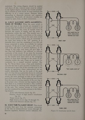
![analytical. The wiring diagram should be studied and above all else, common sense must be utilized to the highest degree. Consider the trouble possibili- ties in relation to each circuit. In most instances the difficulty is of a mmor nature. Hesitate before proceeding to dismantle intricate and expensive components. Practically all electrical troubles are caused by open, loose, or short connections. 91. X-RAY MACHINE UNITS—MANIFESTA- TIONS OF TROUBLE. When the main switch is closed and none of the circuits are energized it is obvious that the trouble is at a point common to all circuits. Therefore, the cause of trouble must be between the source of supply and the point of distribution within the unit. This trouble may be in the source of supply; connections at the source; failure of one or more fuses in the unit; main switch or the circuit breaker (which may be connected in the main line) being in the “‘off” position. It is desirable that a test set, consisting of two 110 volt lamps connected in series, be available for testing purposes. If the set is used across a 220 volt line each lamp will burn at normal brilliancy; if the voltage is 110 volts, each lamp will give light at less than half brilliancy but sufficient to indicate continuity of the circuit. If one tests the Incoming line at the control stand one should be able to local- ize the trouble from there back to the energizing source, or from there through to the center of dis- tribution withm the unit. Fuses can be tested for continuity by a crossed terminal method. (See fig. 72.) Never throw away a fuse until absolutely sure that the fuse is open circuited. Furthermore, do not discard an open fuse of the cartridge type in the theater of operations where replacements are not readily obtainable. Use can be made of the good part of a fuse link as a protection device by reducing the cross section of the fuse wire or link to approxi- mately the same thickness as that of the effective part of the normal fuse. When replacing fuses be sure that the current carrying capacity of the new fuse is of the proper value. A burnt out fuse implies the fact that there is an overload beyond it. This condition may be located by checking each individual circuit of the unit. The various circuits of X-ray units may be considered for trouble analyses in the follow- ing manner: X-ray tube filament circuit (fig. 25). Primary circuit of high tension transformer (fig. 26). Timer circuit (fig. 27). High tension circuit (figs. 31 through 33). Valve tube filament circuits (fig. 33). 92. X-RAY TUBE FILAMENT CIRCUIT. This circuit includes that part from the primary connection at the line or autotransformer source through the 72 TEST LAMPS FAIL TO LIGHT, INDICATING “BURNED OUT FUSE” = O > Le] ———— —— TEST LAMPS FAIL TO LIGHT, INDICATING “BURNED OUT FUSE” THIRD STEP](https://iiif.wellcomecollection.org/image/b32174457_0082.jp2/full/800%2C/0/default.jpg)


 No text description is available for this image
 No text description is available for this image
 No text description is available for this image