Specification of William Church : steam boilers and propellers for vessels.
- Church, William
- Date:
- 1854
Licence: Public Domain Mark
Credit: Specification of William Church : steam boilers and propellers for vessels. Source: Wellcome Collection.
9/20 page 7
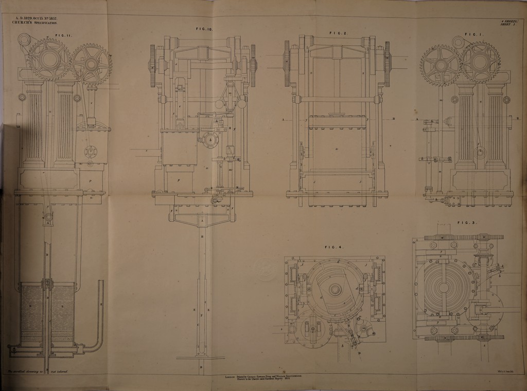
![Church's Improvements in Steam Boilers and Propelling Machinery. and consequently d will be thrown open at the same time the lower valve closing, when all the steam above the pressure of the atmosphere will escape by the passage b. But on the pressure of the atmosphere and the steam becoming nearly equalized, the valve d will fall and close by its gravity, 5 the connecting link at the same time opening the lower valve e, when the remaining part of the steam will be free to pass off by the passage e to the condensor, where it may be acted upon by the jet of water in the usual way. My improvement in the construction and arrangement of the paddles or wheels for propelling ships, boats, and other vessels consists in the following combina- ] 0 tion :—I employ two wheels, each having a series of bent paddles, revolving on a common axle but in opposite directions. These wheels are surrounded each by a cylindrical rim, to which the peripheries of the paddles are attached. Fig. 14 is a front view of one of the paddle wheels, with the cylindrical rim a, a, a, surrounding it; Fig. 15 is a longitudinal representation of the two 15 paddle wheels, the rims being cut in section perpendicularly through their diameters, for the purpose of shewing the construction of the wheels within. I sometimes employ the two wheels with bent paddles, as represented in the two last-mentioned Figures, revolving in opposite directions within a fixed cylinder. It is only necessarv to observe that the axis of the wheels is intended to be 20 placed paraded to the keel of the vessel, and they may be driven by any of the ordinary modes of driving two wheels upon the same axle in opposite directions. My improvements in boilers applicable to steam engines consist, in the first place, in adapting a series of vessels arranged as shewn in the Drawings, 25 of which Fig. 16 is a front view, exhibiting the caps of the several vessels, and also the fire door, ash pit, and the several doors for clearing the flues; Fig. 17 is a top view of the same, the roof of the casing being removed, in order to shew the three upper vessels, and the manner of uniting them together, that is, by bolting them to flanges. Fig. 18 is a horizontal section, 30 taken through the center of the lower vessels on a line with the furnace; and Fin*. 19 is a vertical section, taken transversely through the series of vessels a being the furnace; b 1, b 2, b 3, b 4, b 5, b 6, and b 7, the several vessels occupied with water and steam; and cl, c2, and co, the flues leading from the furnace to the chimney. Fig. 20 is a section of the boiler, taken through the front plate, parallel to its plain, shewing the passages of communication <Z, d, d, for water and steam from one vessel to another. These connecting passages lead through the flanges c, e, e, surrounding the ends of the vessels, as above said, the passages as well as the flanges being east with the front plate /, /, /, seen in Fig. 17 & 18. The water is introduced into the boiler](https://iiif.wellcomecollection.org/image/b30743576_0009.jp2/full/800%2C/0/default.jpg)