Specification of George Henry Birkbeck : trusses or bandages, and pessaries to be used therewith.
- Birkbeck, George Henry.
- Date:
- 1862
Licence: Public Domain Mark
Credit: Specification of George Henry Birkbeck : trusses or bandages, and pessaries to be used therewith. Source: Wellcome Collection.
8/12 page 6
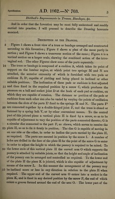
![jBirkbecJcs Improvements in Trusses, Bandages, <Sfc. curved arm 0 is formed with a spherical joint r, which supports the intra- vaginal rod It, consisting of a tube r1 (formed (with a spherical end r), marked with divisions, which indicate the respective heights to which the hollow bowl or pessary X can be raised. Around this there is another tube s, formed into a fork s1 at the upper end, to which the hollow bowl or pessary X is jointed. 5 ]n the interior of the tube there is a screw rod c, which screws in a socket, the upper part of which is forked, and is also jointed to the hollow bowl or pessary X, and by giving motion to this screw by means of a screw nut e at the lower end, the inclined position of the hollow bowl or pessary may be varied. An internal helical spring is inserted in the tube to impart the vertical elasticity 10 necessary to the intravaginal rod to accommodate itself to any movement or change of position of the parts. The position of the tube s surrounding the tube rx is not changed in relation thereto by reason of the projection a soldered to the part u entering a groove a\ as shewn at Figure 4. The screw u is combined with the tube s, and with the part i, which is retained in the 15 groove x1 of the tube z, in order that the two parts may move simultaneously. The lower part of the tube x is grooved to receive the button k, cut with teeth to act as a catch for the sliding bolt l to lock the parts when in position. The piece v acts as a guide to the screw rod c, the pitch of which is the same as that of the screwed piece v, and which rod c works in the tube d, to which are 20 jointed the forked arms dl attached to the oval bowl X. The tube d fits into the tube v, as seen at Figure 4. A grooved collar c\ formed at the lowrer part of the rod c, is arranged to receive the ends of the two pins n, which allow of free rotatory movement, but which at the same time prevent any alteration of the vertical position. The power of working the rod c is furnished by means 25 of the button e fixed on the end of the rod /, which is connected to the rod c by means of projections c2. The slotted rod h allows the rod c as well as the piece to which it is fixed to rise or descend as required, and as is hereafter explained. The spiral spring i, placed between the piece v and the part x, serves to give the vertical elasticity necessary to the intravaginal rod in order 30 that it may accommodate itself to the movements of the body. The spring i always remains in the same degree of tension whatever be the height to which the bowl or instrument X has been raised by the tube s and parts connected therewith. From the previous description it will be seen that by the combination of the 35 several parts, all the variations necessary for the various functions of the pessary may be obtained. The powTer of inclining the bowl or instrument X to any angle required is obtained by turning the milled button e9 which is fixed on the rod/and tied by the pins c1 to the screw rod c. This rod c causes the tube d](https://iiif.wellcomecollection.org/image/b30748185_0008.jp2/full/800%2C/0/default.jpg)