Specification of John Chanter and John Gray : furnaces of steam boilers.
- Chanter, John.
- Date:
- 1854
Licence: Public Domain Mark
Credit: Specification of John Chanter and John Gray : furnaces of steam boilers. Source: Wellcome Collection.
4/12 (page 2)
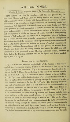
![Chavta- ^ Gray's Improved Furnace for Consvming Smoke, ^c. HOW KHCW YE, tliat in compliance with the said proviso, we, the sai.l John Chanter and John Gray, do hereby declare the nature of our ^aid Invention to consist, as in the said Letters Patent is expressed, of a new combination of parts forming an improved furnace for consuming smoke and economizing fuel, applicable to locomotive carriages, steam boats, and other 5 useful purposes, by which combination of parts we construct an additional fire grate, and are enabled to expose additional water surfaces to the action of heat, and consequently to obtain an increase of steam without a corresponding increase of fuel, and are also enabled to use a cheaper description of fuel than that at present adapted under particular circumstances, as by the arrangement 10 herein-after described the smoke and other vapours arising from uncarbonized fuel is subjected to ignition and reduced to a state of perfect combustion or nearly so; and in further compliance with the said proviso, we, the said John Chanter and John Gray, do hereby describe the manner in which our said Invention is to be performed by the following statement thereof, reference 15 being had to the Drawings annexed, and to the figures and letters marked tliei’on, that is to say:— Desceiption of the Deawings. FjV. 1 is a sectional elevation longitudinally of the furnace or fire box as a|>p]icd to a locomotive engine, divided at the horizontal line A, A, in 20 Figure 4, herein-after mentioned. Fig. 2 is a transverse section, divided at the vertical line B, B, Figure 1, and looking to the end of the fire box opposite the fire doors H, 1. Fig. 3 is a transverse section, divided at the vertical line at C, C, Fig. 1, and looking in the direction of or towards the fire doors II, I. Fig. 4 is a plan of the water chamber passing through the furnace, as herein- 25 after described, as shewn at the lines D, D, Fig. 1. The Drawings are made on a scale of one inch and a half to a foot, but we do not confine ourselves to the precise dimensions or form of any of the parts. The same letters of reference where used in different Figures refer to the same parts. E, F, lig* 1? is the furnace or fire box constructed by external and internal metallic cases a, a, and 5, 5, in the mode usually adopted; c, c, being the water spaces between the inner and the outer casings of the fire box. The interior of the furnace or fire box is divided into two compartments E, E, by a water vessel or chamber passing through the furnace, and formed partly of tubular channels or hollow bars e, e, and partly by a water chamber d, d, and thus forming a w ater way or communication from the water space at e, to the water space atp. The hollow bars are constructed of anv convenient number, and may be made](https://iiif.wellcomecollection.org/image/b30752930_0004.jp2/full/800%2C/0/default.jpg)