Improvements in and relating to beds and fittings for the use of invalids and the like / [William Abbot Nason].
- Nason, William Abbot.
- Date:
- 1902
Licence: Public Domain Mark
Credit: Improvements in and relating to beds and fittings for the use of invalids and the like / [William Abbot Nason]. Source: Wellcome Collection.
1/8
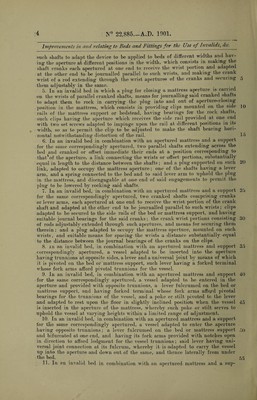
![N° 22,885 A.D. 1901 Date of Application, 12th Nov., 1901—Accepted, 20th Feb., 1902 COMPXETE SPECIFICATION. Improvements in and relating to Beds and Fittings for the Use of Invalids and the like. I, William Abbot Nason, residing at Algonquin, Kane County, Illinois, United States of America, Physician, do hereby declare the nature of this inven¬ tion and in what manner the same is to he performed, to be particularly described and ascertained in and by the following statement. The purpose of this invention is to provide an invalid bed with improved means for accommodating a bedridden patient and permitting surgical attention to such patient without the use of bed-pansi or like appliances which are other¬ wise necessary. The invention consists of new and simplified means for operating a plug or closure in a mattress aperture, and for upholding a vessel in such ^ aperture, and of withdrawing the same without disturbing the patient, and of specific details of construction which are set out in the claims. In the drawings Figure 1 is a side elevation of an invalid bed having my invention, the mattress plug being shown in the aperture of the mattress, and , „ the vessel carrier and vessel being out of operation. Figure 2 is a longitudinal section showing the mattress plug withdrawn and the vessel held in operative position by the carrier. Figure 3 is a transverse section at the line 3—3 on Figure 2, omitting the vessel and carrier. Figure 4 is a partly sectional detail elevation of the crank shaft structure, 20 each pivotal bearing or junction being shown on axial section. Figure 5 is a side elevation of a modified vessel carrier. Figure 6 is a detail elevation showing the pivot bearing clamp applied to a cylindrical rail. A is a mattress having an aperture, a, adapted to be occupied by the plug A1. 2ft B represents the mattress1 support, which is shown as a common form of woven- wire spring, having aperture corresponding to that of the mattress. B1, B1, are the side rails of the mattress supporting spring. C is a support for the plug A1, which is preferably made of perforated sheet metal rendered more rigid longi¬ tudinally by angle iron bars, C1, C1, the whole structure, consisting of said plate 30 and bars, constituting a flat link which connects the wrists of cranked shafts hereinafter described, by which the plug is operated. For convenience of con¬ struction and adaptation to beds of different widths and having the aperture at different positions in the width, I have shown these cranked shafts as made up of adjustable parts. The description of one of the cranked ahsfts will suffice for 35 both. Each shaft consists of two crank elements, D, D, which at one end are adapted to be journalled in line on opposite sides of the bed, the boss or hub l)1 of each element constituting or representing the shaft proper, the boss I)2 at the opposite end being apertured parallel to the shaft axis to receive the adjustable Wrist I)3. Such wrist is a rod, whose length is substantially the width of the 40 narrowest bed to which the device may be applied, the range of adjustment which it may have m and through the boss I)2 being from a short engagement sufficient to permit it to be secured by the set screw d3, to a maximum protrusion through the boss, which may be not- farther than the end of the boss I)1; this range of adjustment being at least half the difference between the width of the nailowest 45 and widest bed to which said device may be applied, so that by utilizing such [Price 8ff.]](https://iiif.wellcomecollection.org/image/b3074040x_0001.jp2/full/800%2C/0/default.jpg)