A systematic handbook of volumetric analysis, or, The quantitative estimation of chemical substances by measure, applied to liquids, solids, and gases : adapted to the requirements of pure chemical research, pathological chemistry, pharmacy, metallurgy, manufacturing chemistry, photography, etc., and for the valuation of substances used in commerce, agriculture and the arts / by Francis Sutton.
- Francis Sutton
- Date:
- 1882
Licence: Public Domain Mark
Credit: A systematic handbook of volumetric analysis, or, The quantitative estimation of chemical substances by measure, applied to liquids, solids, and gases : adapted to the requirements of pure chemical research, pathological chemistry, pharmacy, metallurgy, manufacturing chemistry, photography, etc., and for the valuation of substances used in commerce, agriculture and the arts / by Francis Sutton. Source: Wellcome Collection.
Provider: This material has been provided by University of Bristol Library. The original may be consulted at University of Bristol Library.
361/508 page 345
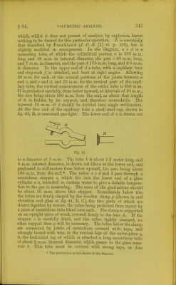
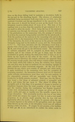
![which, whilst it does not permit of analysis by explosion, leaves nothing to be desired for this particular operation. It is essentially that described by Frankland {J. C. S. [2] vi. p. 109), but is slightly modified in arrangement. In the diagram, a c d is a. measuring tube, of which the cylindrical portion a is 370 m.m. long, and 18 m.m. in internal diameter, the part c 40 m.m. long, and 7 m.m. in diameter, and the part d 175 m.m. long, and 2'5 m.m. in diameter. To the upper end of d a tube, with a capillary bore and stop-cock /, is attached, and bent at right angles. Allowing 20 m.m. for each of the conical portions at the joints between a and c, and c and d, and 25 m.m. for the vertical part of the capil- lary tube, the vertical measurement of the entire tube is 650 m.m. It is graduated carefully, from below upward, at intervals of 10 m.m., the zero being about 100 m.m. from the end, as about that length of it is hidden by its support, and therefore unavailable. The topmost 10 m.m. of d should be divided into single millimeters. At the free end of the capillary tube a small steel cap, shown in fig. 45, B, is cemented gas-tight. The lower end of a is drawn out B Fig. 45. to a diameter of 5 m.m. The tube b is about 1-2 meter long, and 6 m,m. internal diameter, is drawn out like a at the lower end, and graduated in millimeters from below upward, the zero being about 100 m.m. from the end.* The tubes a c d and b pass through a caoutchouc stopper o, which fits into the lower end of a glass cylinder n ?z, intended to contain water to give a definite tempera- ture to the gas in measuring. The zeros of the graduations should be about 10 m.m. above this stopper. Immediately below this the tubes are firmly clasped by the wooden clamp jj (shown in end elevation and plan at fig. 44, B, C), the two parts of which are drawn together by screws, the tubes being protected from injury by a piece of caoutchouc tube fitted over each. The clamp is supported on an upright piece of wood, screwed firmly to the base A. If the stopper 0 is carefully fitted, and the tubes tightly clamped, no other support than p will be necessary. The tubes below the clamp are connected by joints of caoutchouc covered with tape, and .strongly bound with wire, to the vertical legs of the union-piece q, to the horizontal leg of which is attached a long caoutchouc tube of about 2 m.m. internal diameter, which passes to the glass reser- voir t. This tube must be covered with strong tape, or (less * The graduation is not shown in the diagi-am.](https://iiif.wellcomecollection.org/image/b21443658_0361.jp2/full/800%2C/0/default.jpg)