Improvements in coin-actuated medical batteries / [Nelson Marshall Watson].
- Watson, Nelson Marshall.
- Date:
- 1902
Licence: Public Domain Mark
Credit: Improvements in coin-actuated medical batteries / [Nelson Marshall Watson]. Source: Wellcome Collection.
1/8
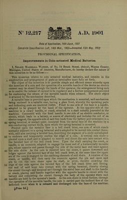
![N° ] 2,217 A.I). 1901 Date of Application, 14th June, 1901 Complete Specification Left, 14th Mar., 1902—*Accepted, 15th May, 1902 PROVISIONAL SPECIFICATION. Improvements in Coin-actuated Medical Batteries. I, Nelson Marshall Watson, of No. 72 Brush Street, Detroit, Wayne County, Michigan, United States of America, Manufacturer, do hereby declare the nature of this invention to be as follows :— This invention relates to coin actuated medical batteries, and consists in the t construction and arrangement of parts as hereinafter more fully set forth. The object of the invention is to provide simple and efficient means whereby upon the insertion of a coin and the operation of a movable handle of the device an electric current may be closed through the hands of the operator, the arrangement being such as to enable the volume of current to be regulated and a further arrangement provided IQ for cushioning the return of the movable handle when released. The above object is attained by the mechanism described. A suitable base is provided upon which the mechanism is mounted, said mechanism being enclosed in a suitable case, having a glass front, whereby the operating parts and indicating scale are rendered visible. Fixed to one side of the base is a handle, 15 adapted to be grasped by the hand of the operator. At the opposite side of the machine is a rotary handle, or crank, attached to a shaft suitably journaled in the machine. Connected with the fixed handle is one side of an electric conductor, or circuit, which leads to a battery, or source of electricity and includes the coil of an electro-magnet, the opposite side ot said line leads from the battery and terminates in a 2Q spring terminal, or contact point, insulated from the metal base of the machine by a non-conducting contact block, upon which the spring terminal is mounted. Pivoted upon the metallic base is a bell crank lever, one arm of which stands normally adjacent to a spring terminal and is adapted to be moved into contact there¬ with, said arm carrying a beveled face, describing the segment of a circle and adapted 25 to embrace and temporarily confine the edge of a coin. A vertical coin shute is pivoted upon a shaft and is adapted to receive and direct the coin into contact with the beveled face of the bell crank lever. Upon the shaft carrying the crank, or handle, is an eccentric, adapted to engage the inner end of a horizontrally movable pin, whose opposite end passes through the side of the metal base and bears against 30 the* coin shute. As the coin is directed into the shute, it passes downward and ledges against the beveled face of the bell crank lever, at the same time the upper arc of the coin is engaged by the confining channels of said shute. A rotation of the crank, or handle, will then carry the eccentric against the pin and cause said pin to tilt the coin shute upon its shaft, or pivot, thereby crowding the 35 edge of the coin against the beveled face of the bell crank lever and forcing the end of said lever into contact with the spring terminal, thereby closing the circuit through said terminal and through the metal base and shaft to the handle or crank, placing said handle together with the opposite handle in circuit with the battery and completing the circuit through the body of the operator when said 40 handles are held by the operator’s hands. As the coin shute is tilted further, through the operation of the movable handle, the coin is carried past the inclined face of the bellcrank lever when it is released and discharged into the base of the machine, [Price 8d.]](https://iiif.wellcomecollection.org/image/b30739780_0001.jp2/full/800%2C/0/default.jpg)