Second report of the Departmental Committee appointed to inquire into the ventilation of factories and workshops. Pt. 1, Report.
- Great Britain. Home Office. Committee on Ventilation of Factories and Workshops.
- Date:
- 1907
Licence: Public Domain Mark
Credit: Second report of the Departmental Committee appointed to inquire into the ventilation of factories and workshops. Pt. 1, Report. Source: Wellcome Collection.
19/140 (page 5)
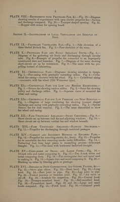
![2 PLATE VIII.—Exprriments wird Prorenier Fan, &c.—Fig. 19.—Diagram showing results of experiments with open electric propeller fan—Suction and discharge compared. Fig. 20.— Trumpet shaped opening. Fig. 21. —Hopper with screen for opening board. Section I].—Ixtiustrations or Locan VENTILATION AND REMOVAL OF Dust. PLATE IX.—Properrer Ventizatinc Fay.—Fig. 1.—Side elevation of a three-bladed 24-inch fan. Fig. 2.—Face elevation of the same. PLATE X.—Propretter Fans ayy Bapry Arrancep Ducts.—Fig. 5.— Diagram of fan gathering air freely and discharging through circular tube. Vig. 6—Example of propeller fan connected to an improperly constructed duct and branches. Fig. 7.—Diagram of the same showing short-circuit set up by resistances. Fig. 8.—The same with fan pro- pelling instead of exhausting. PLATE XI.--Centrirucan Fans.—Diagrams showing mistakes in design. Fig. 1.—Fan-casing with gradually extending radius. Fig. 2.—Cylin- drical fan-casing—eccentric with fan wheel. Fig. 3.— Cylindrical casing —concentric with tan wheel (Old Winnower type). PLATE Xla.—Centrirucat Fans ror Low anp Mepium ResristancEes.— Fig. 1..-—Sirocco fan showing suction orifice. Fig. 2.—Same fan showing pulley and discharge orifice, Fig. 3.—Separate views of mounted fan wheel and casing. PLATE XIs.—Cenrrirucat Fan ror Low Pressure anp Dust REMovat.— Fig. 1.—Diagram of large ventilating fan showing trumpet shaped discharge and casing with gradually extending radius. Fig. 2.—Special Sirocco fan for dust removal. Fig. 3—The same dismantled to show fan wheel and casing. PLATE XII.—Fans Unsuitasty Arrancep—Suort Circuirine.—Fig. 9.— Short circuit set up between wall fan and adjoining windows. Fig. 10.— Short circuit set up between vertical fan and window beneath. PLATE XIII.—Fans Unsuirasry Arrancep—BarritepD DIscHARGE.— Fig. 11.—Propeller fan discharging through restricted passages. PLATE XIV.—Correcr anp Incorrect Mersops or Encasinc Fays.— Fig. 12.—Propeller fan removing smoke, &c., freely. Fig. 18.—Propeller fan in unsuitable fan-box removing smoke under difficulties. Fig. 14.— Extracting dust from large plates in enamelling process-—downward draught. Fig. 15.—The same with horizontal backward draught. PLATE XV.—Comparison or SMALL AnD -Larce Prrinc.—Fig. 16.— 10-inch tube and metal composing it. Fig. 17.—Ten 3-inch tubes and metal composing them. Fig. 18.—Flat rectangular duct and metal used in making it. Fig. 19.—Square duct and metal composing it. Fig. 20.— Blocking up tubes by filtering grids or gratings. | PLATE XVI.—Deraus or Ducr Construction, Air Guipes, Firrers, &c.— Fig. 21.—Stove pipe elbow. Fig. 22.—Short bend. Fig. 23.—Long bend. Fig. 24.—Butt joint in pipe. Fig. 25.—Lap joint in pipe. Fig. 26.—Forked junction or breeches joint. Fig. 27.—<Air valve or cut-off. Fig. 28.—Armbhole for inspection. Fig. 29.—Conical hood. Fig. 30.—Trumpet-mouthed hood. Fig. 31.—Bell-mouthed hood. — Fig. 32.—Pyramidical hood. Figs. 33 and 34.—-Large and small hoods compared. Fig. 35.—Porch hood. Fig. 86.—Curtained porch](https://iiif.wellcomecollection.org/image/b32182107_0019.jp2/full/800%2C/0/default.jpg)