Second report of the Departmental Committee appointed to inquire into the ventilation of factories and workshops. Pt. 1, Report.
- Great Britain. Home Office. Committee on Ventilation of Factories and Workshops.
- Date:
- 1907
Licence: Public Domain Mark
Credit: Second report of the Departmental Committee appointed to inquire into the ventilation of factories and workshops. Pt. 1, Report. Source: Wellcome Collection.
58/140 (page 26)
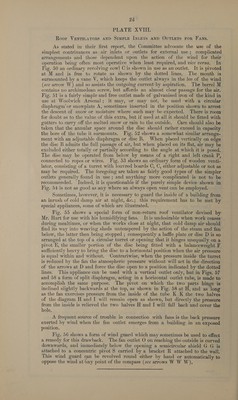
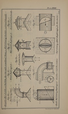
![PLATE XVIII. Roor VENTILATORS AND SIMPLE INLETS AND OuTLETS FoR FANS. As stated in their first report, the Committee advocate the use of the simplest contrivances as air inlets or outlets for external use ; complicated arrangemeuts and those dependent upon the action of the wind for their operation being often most operative when least required, and vice versa. In — Fig. 50 an ordinary revolving cow] C is shown in use as an outlet. It is pivoted at M and is free to rotate as shown by the dotted lines. The mouth is surmounted by a vane V, which keeps the outlet always in the lee of the wind (see arrow W) and so assists the outgoing current by aspiration. The barrel M contains no archimedean screw, but affords an almost clear passage for the air. Fig. 51 is a fairly simple and free outlet made of galvanised iron of the kind in use at Woolwich Arsenal; it may, or may not, be used with a circular diaphragm or snowplate A, sometimes inserted in the position shown to arrest the descent of snow or moisture where such may be expected. There is room for doubt as to the value of this extra, but if used at all it should be fitted with gutters to carry off the melted snow or rain to the outside. Care should also be taken that the annular space around the disc should rather exceed in capacity the bore of the tube it surmounts. Fig. 52 shows a somewhat similar arrange- ment with an adjustable diaphragm or disc B, When placed vertically on edge the disc B admits the full passage of air, but when placed on its flat, air may be excluded either totally or partially according to the angle at which it is posed. The disc may be operated from below by means of a right and left crank P, connected to ropes or wires. Fig. 53 shows an ordinary form of wooden venti- lator, consisting of a turret with louvred boards C, C, either adjustable or not as may be required. The foregoing are taken as fairly good types of the simpler outlets generally found in use; and anything more complicated is not to be recommended. Indeed, it is questionable if the purely simple device shown in Fig. 54 is not as good as any where an always open vent can be employed. Sometimes, however, it is necessary to guard the inside of a building from an inrush of cold damp air at night, &c.; this requirement has to be met by special appliances, some of which are illustrated. Fig. 55 shows a special form of non-return roof ventilator devised by Mr. Hart for use with his humidifying fans. It is undesirable when work ceases during mealtimes, or when the works close at night, that cold damp air should find its way into weaving sheds untempered by the action of the steam and fan below, the latter then being stopped ; consequently a bafile plate or dise D is so arranged at the top of a circular turret or opening that it hinges unequally on a pivot E, the smaller portion of the dise being fitted with a balanceweight F sufficiently heavy to bring the disc to a horizontal position when the air pressure is equal within and without. Contrariwise, when the pressure inside the turret is reduced by the fan the atmospheric pressure without will act in the direction of the arrows at D and force the disc open to a position indicated by the dotted — lines. This appliance can be used with a vertical outlet only, but in Figs, 57 and 58 a form of split diaphragm, acting in a horizontal outlet tube, is made to accomplish the same purpose. The pivot on which the two parts hinge is inclined slightly backwards at the top, as shown in Fig. 58 at H, and as long as the fan exercises pressure from the inside of the tube K K the two halves of the diagram H and I will remain open as shown, but directly the pressure from the inside is relieved the two halves H and I will fall back and cover the hole, | A frequent source of trouble in connection with fans is the back pressure exerted by wind when the fan outlet emerges from a building in an exposed position, Fig. 56 shows a form of wind guard which may sometimes be used to effect a remedy for this drawback. The fan outlet O on reaching the outside is curved downwards, and immediately below the opening a semicircular shield G G is attached to a concentric pivot 5 carried by a bracket R attached to the wall. This wind guard can be revolved round either by hand or automatically to oppose the wind at tuny point of the compass (see arrows W W W),.](https://iiif.wellcomecollection.org/image/b32182107_0058.jp2/full/800%2C/0/default.jpg)