Improvements in and relating to dental chairs / [Frank Ritter].
- Ritter, Frank
- Date:
- 1897
Licence: Public Domain Mark
Credit: Improvements in and relating to dental chairs / [Frank Ritter]. Source: Wellcome Collection.
1/8
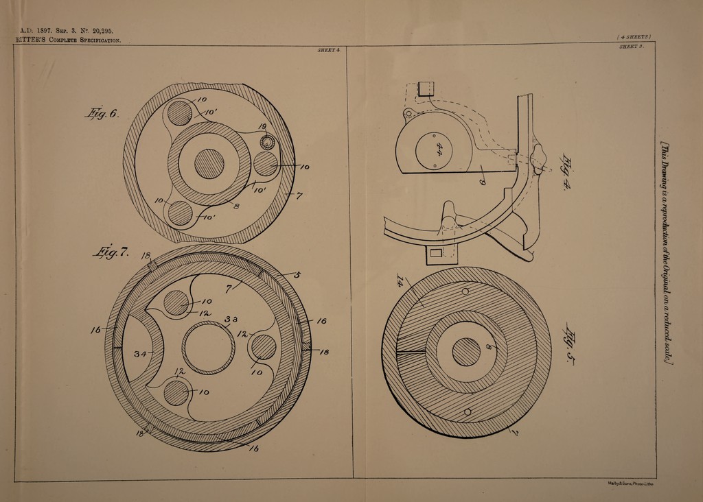
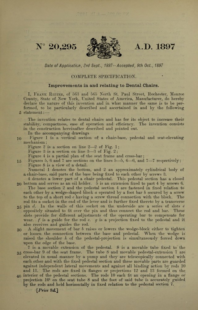
![N° 20,295 A.D. 1897 Date of Application, 3rd Sept., 1897— Accepted, 9th Oct., 1897 COMPLETE SPECIFICATION. Improvements in and relating to Dental Chairs. I, Frank Ritter, of 5G3 and 505 North St. Paul Street, Rochester, Monroe County, State of New York, United States of America, Manufacturer, do hereby declare the nature of this invention and in what manner the same is to be per¬ formed, to be particularly described and ascertained in and by the following 5 statement: — The invention relates to dental chairs and has for its object to increase their stability, compactness, ease of operation and efficiency. The invention consists in the construction hereinafter described and pointed out. In the accompanying drawings ]0 Figure 1 is a vertical section of a chair-base, pedestal and seat-elevating mechanism; Figure 2 is a section on line 2—2 of Fig. 1; Figure 3 is a section on line 3—3 of Fig. 2; Figure 4 is a partial plan of the seat frame and cross-bar; 15 Figures 5, 0 and T are sections on the lines 5—5, 0—0, and T—7 respectively; Figure 8 is a view of a detail. Numeral 1 denotes the bottom, and 2 an approximately cylindrical body of a chair-base, said parts of the base being fixed to each other by screws 3. 4 denotes a lower part of a chair pedestal. This pedestal section has a closed 2() bottom and serves as an oil holder. 5 is an extension fixed to part 4 by screws 0. The base section 2 and the pedestal section 4 are fastened in fixed relation to each other by a wedge-shaped block a operated by a foot bar b secured by a screw to the top of a short rod c having a screw thread connection with the block. The rod fits a socket in the end of the lever and is further fixed thereto by a transverse 25 pin d. In the walls of this socket on the. underside are a series of slots e oppositely situated to fit over the pin and thus connect the rod and bar. These slots provide for different adjustments of the operating bar to compensate for wear, f is a guide for the rod c. g is a projection fixed to the pedestal and it also receives and guides the rod. 30 A slight movement of bar b raises or lowers the wedge-block either to tighten or loosen the connection between the base and pedestal. When the wedge is raised the shoulder h of the pedestal-projection is simultaneously forced down upon the edge of the base. 7 is a movable extension of the pedestal. 8 is a movable tube fixed to the 35 cross-bar 9 of the seat frame. The tube 8 and movable pedestal-extension 7 are elevated in usual manner by a pump and they are telescopically connected with each other and with the fixed pedestal section and these movable parts are guarded against independent lateral movements and against all binding action by rods 10 and 11. The rods are fixed in flanges or projections 12 and 13 formed on the 40 interior of the pedestal sections. The rods 10 each fit an opening in a flange or projection 101 on the seat tube 8 and the foot of said tube is accurately guided by the rods and held horizontally in fixed relation to the pedestal section 7. [Price 8c£.]](https://iiif.wellcomecollection.org/image/b3073681x_0001.jp2/full/800%2C/0/default.jpg)
 No text description is available for this image
 No text description is available for this image
 No text description is available for this image