The microscope and histology / by Simon Henry Gage ... pt. I. The microscope and microscopical methods.
- Simon Henry Gage
- Date:
- 1892
Licence: Public Domain Mark
Credit: The microscope and histology / by Simon Henry Gage ... pt. I. The microscope and microscopical methods. Source: Wellcome Collection.
Provider: This material has been provided by the Harvey Cushing/John Hay Whitney Medical Library at Yale University, through the Medical Heritage Library. The original may be consulted at the Harvey Cushing/John Hay Whitney Medical Library at Yale University.
21/232
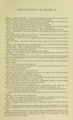
![fig- 9- Tripod Magnifier. The frame holding the lenses may be raised or low- ered (focused) by screwing it up or down in the outside ring. Fig. 10. Stand. That is the mechaical parts of a simple form of compound mi- croscope, with the names of the parts written upon them. Arm. The part connecting the body or tube to the pillar. Base. The part of the stand on which it rests. It should be heavy and so formed that it will give steadiness, and not be in the way of the mirror. Body. The tube and draw-tube together. Also frequently called the lube. Coarse Adjustment. The rack and pinion for moving the tube or body rapidly up or down. Fine Adjustment. The micrometer screw arrangement for moving the body or tube of the microscope slowly up or down. Compressor. One of the pair of light springs to hold the preparation in position on the stage. Flexible Pillar. The pillar of the microscope, with a joint to incline the micro- scope. Mirror. The movable mirror with plane and concave face for lighting the object. Mirror Bar The bar supporting the mirror. Society Screw. The screws at the lower end of the draw-tube and the main tube or body lube for receiving the objective. Statue. The horizontal plate for supporting the object. Subs/age The cylinder below the stage for diaphragms, the illuminator and other substage accessories. Fig. 11. Sectional view of the stage to show the relative position of the prepara- tion and the diaphragms necessary to insure the most satisfactory lighting when a mirror is used. Fig. 12. Section of a dry objective showing working distance and lighting by reflected light. Axis. The optic axis of the objective. B C. Back Combination, composed of a plano-concave of flint glass (F), and a double convex of crown glass (c). I' C, Front Combination. C O si. The cover-glass, object and slide. Mirror. The mirror is represented as above the stage, and as reflecting paral- lel rays from its plane face upon the object. Stage. Section of the stage of the microscope. W. The Working Distance, that is the distance from the front of the objective to the object when the objective is in focus (',, 38). Fig. 13. Sectional view of an Immersion Adjustable Objective, and the object lighted with axial or central and with oblique light. Axis. The optic axis of the objective. BC, M C, F C. The back, middle and front combinations of the objective. In this case the front is not a combination, but a single plano-convex lens. A B. Parallel rays reflected by the mirror axially or central])- upon the object. C. Ray reflected to the object obliquely. I. Immersion fluid between the front of the objective and the cover-glass or ob- ject O). Mirror. The mirror of the microscope. O. Object. It is represented without a cover-glass. Ordinarily objects are cov- ered whether examined with immersion or with dry objectives. Stage. Section of the stage of the microscope. Fig. 14. Diagram showing how to place a cover-glass upon an object with fine forceps. Fig. 15. Diagram showing how to enclose the lines of a micrometer, or of some part of a preparation by a small ring to facilitate finding it under the microscope li j2). Fig. 16. Double eye-shade (jj 73). This is made by cutting a hole slightly larger than the tube near one edge. A rubber band is then used to loop around the tube and holding the screen from falling over in front. It is desirable to have the screen covered with velveteen.](https://iiif.wellcomecollection.org/image/b21023840_0021.jp2/full/800%2C/0/default.jpg)