Improved combined stretcher and ambulance seat, more particularly applicable for use in mines / [Charles Sebastian Smith].
- Smith, Charles Sebastian.
- Date:
- 1888
Licence: Public Domain Mark
Credit: Improved combined stretcher and ambulance seat, more particularly applicable for use in mines / [Charles Sebastian Smith]. Source: Wellcome Collection.
1/10
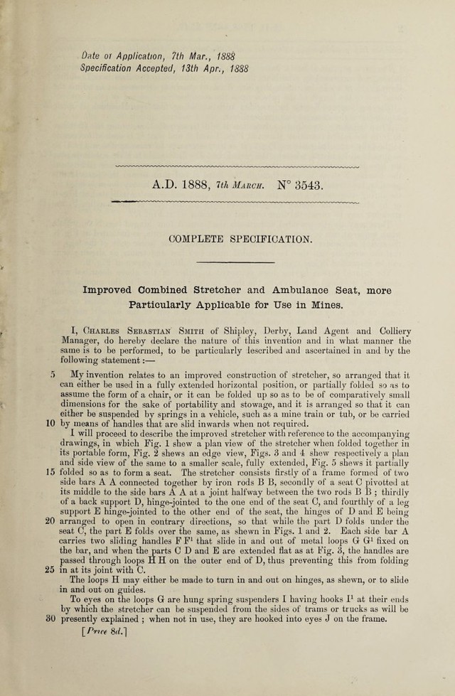
![Date or Application, 7th Mar., 1888 Specification Accepted, 13th Apr., 1888 A.D. 1888, 7th March. N° 3543. COMPLETE SPECIFICATION. Improved Combined Stretcher and Ambulance Seat, more Particularly Applicable for Use in Mines. I, Charles Sebastian Smith of Shipley, Derby, Land Agent and Colliery Manager, do hereby declare the nature of this invention and in what manner the same is to be performed, to be particularly lescribed and ascertained in and by the following statement:— 5 My invention relates to an improved construction of stretcher, so arranged that it can either be used in a fully extended horizontal position, or partially folded so as to assume the form of a chair, or it can be folded up so as to be of comparatively small dimensions for the sake of portability and stowage, and it is arranged so that it can either be suspended by springs in a vehicle, such as a mine train or tub, or be carried 1.0 by means of handles that are slid inwards when not required. I will proceed to describe the improved stretcher with reference to the accompanying drawings, in which Fig. 1 shew a plan view of the stretcher when folded together in its portable form, Fig. 2 shews an edge view, Figs. 3 and 4 shew respectively a plan and side view of the same to a smaller scale, fully extended, Fig. 5 shews it partially 15 folded so as to form a seat. The stretcher consists firstly of a frame formed of two side bars A A connected together by iron rods B B, secondly of a seat C pivotted at its middle to the side bars A A at a joint halfway between the two rods B B ; thirdly of a back support D, hinge-jointed to the one end of the seat C, and fourthly of a leg support E hinge-jointed to the other end of the seat, the hinges of D and E being 20 arranged to open in contrary directions, so that while the part D folds under the seat C, the part E folds over the same, as shewn in Figs. 1 and 2. Each side bar A carries two sliding handles F F1 that slide in and out of metal loops G G1 fixed on the bar, and when the parts C D and E are extended flat as at Fig. 3, the handles are passed through loops H H on the outer end of D, thus preventing this from folding- 25 in at its joint with C. The loops H may either be made to turn in and out on hinges, as shewn, or to slide in and out on guides. To eyes on the loops G are hung spring suspenders I having hooks I1 at their ends by which the stretcher can be suspended from the sides of trams or trucks as will be 30 presently explained ; when not in use, they are hooked into eyes J on the frame. [Price &/.]](https://iiif.wellcomecollection.org/image/b30738568_0001.jp2/full/800%2C/0/default.jpg)