Improvements relating to the mounting of artificial teeth for exhibition and similar purposes / [Henry Daniel Justi].
- Justi, Henry Daniel.
- Date:
- 1901
Licence: Public Domain Mark
Credit: Improvements relating to the mounting of artificial teeth for exhibition and similar purposes / [Henry Daniel Justi]. Source: Wellcome Collection.
1/4
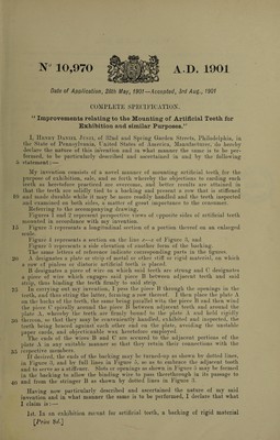
![W 10,970 AD. 1901 Date of Application, 28th May, 1901—Accepted, 3rd Aug., 1901 COMPLETE SPECIFICATION. u Improvements relating to the Mounting of Artificial Teeth for Exhibition and similar Purposes.’’ I, Henry Daniel Jusri, of 32nd and Spring Garden Streets, Philadelphia, in the State of Pennsylvania, United States of America, Manufacturer, do hereby declare the nature of this invention and m what manner the same is to he per¬ formed, to he particularly described and ascertained in and by the following 6 statement: — My invention consists of a novel manner of mounting artificial teeth for the purpose of exhibition, sale, and so forth whereby the objections to carding such teeth as heretofore practiced are overcome, and better results are attained in that the teeth are solidly tied to a backing and present a row that is stiffened 10 and made durable while it may be more readily handled and the teeth inspected and examined on both sides, a matter of great importance to the consumer. Referring to the accompanying drawing, Figures 1 and 2 represent perspective views of opposite sides of artificial teeth mounted in accordance with my invention. 15 Figure 3 represents a longitudinal section of a portion thereof on an enlarged scale. ! Figure 4 represents a section on the line x■—x of Figure 3, and Figure 5 represents a side elevation of another form of the backing. The same letters of reference indicate corresponding parts in the figures. 20 A designates a plate or strip of' metal or other stiff or rigid material, on which a row of pinless or diatoric artificial teeth is placed. 13 designates a piece of wire on which said teeth are strung and C designates a piece of wire which engages said piece B between adjacent teeth and said strip, thus binding the teeth firmly to said strip. 25 In carrying out my invention, I pass the piece B through the openings in the teeth, and thus string the latter, forming a row thereof. I then place the plate A on the backs of the teeth, the same being parallel witn the piece B and then wind the piece C spirally around the piece B between adjacent teeth and around the d1 ate A, whereby the teeth are firmly bound to the plate A and held rigidly 30 thereon, so that they may be conveniently handled, exhibited and inspected, the teeth being braced against each other and on the plate, avoiding the unstable paper cards, and objectionable wax heretofore employed. The ends of the wires B and C are secured to the adjacent portions of the plate A in any suitable manner so that they retain their connections with the 35 jcspective members. If desired, the ends of the backing may be turned-up as shown by dotted lines, in Figure 3, and by full lines in Figure 5, so as to embrace the adjacent tooth and to serve as a stiffener. Slots or openings as shown in Figure 5 may be formed in the backing to allow the binding wire to pass therethrough in its passage to 40 and from the stringer B as shown by dotted lines in Figure 3. Having now particularly described and ascertained the nature of my said invention and in what manner the same is to be performed, I declare that what I claim is : —• 1st. In an exhibition mount for artificial teeth, a backing of rigid material \Price 8t/.]](https://iiif.wellcomecollection.org/image/b30737370_0001.jp2/full/800%2C/0/default.jpg)