Improvements in devices for filling and capping capsules / [Frank Burgett Grove].
- Grove, Frank Burgett.
- Date:
- 1897
Licence: Public Domain Mark
Credit: Improvements in devices for filling and capping capsules / [Frank Burgett Grove]. Source: Wellcome Collection.
1/4
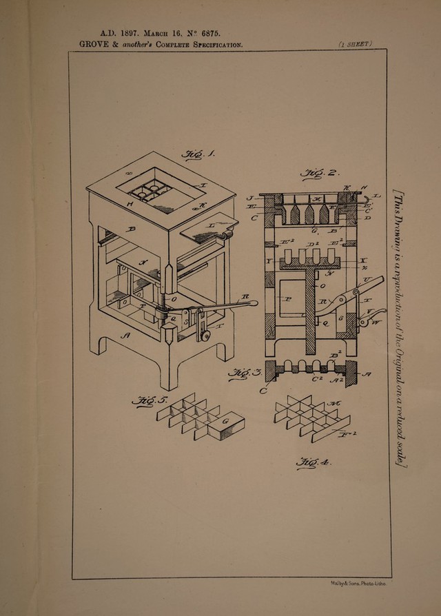
![Date of Application, 16th Mar., 1897— Accepted, 9th Oct., 1897 COMPLETE SPECIFICATION. Improvements in Devices for Filling and Capping Capsules. We, Frank Burgett Grove, of 63 North. Main Street, and George Mitchell, of 36 W. Third Street, both of Mansfield, in the County of Richland, and State of Ohio, United States of America, Gentlemen, do hereby declare the nature of this' invention and in what manner the same is to be performed, to be particularly 5 described and ascertained in and by the following statement: — Our invention relates to improvements in capsule machines, and the object of our invention is the provision of a machine of the character and for the purpose named, which will fill and make the capsule in a rapid and perfect manner; which will be compact in order that it will occupy little space and be easily transported 10 from place to place and which will possess merit in point of simplicity, durability and inexpensiveness of construction and thereby prove entirely practical. Toi attain the desired objects the invention consists of a capsule machine embodying novel features of construction and combination of parts substantially as disclosed herein. 15 Figure 1 represents a perspective view of the machine. Figure 2 represents a vertical central sectional view. Figure 3 represents a detail sectional view of one of the molds, and Figures 4 and 5 represent detail perspective views of the cells or dividing cases. Referring by letter to the drawing: — 20 A designates the frame, which is of open rectangular shape having at the top portion B, the ledges or supports C C1, the ledges or supports E2, the guide frame P, having the guides Q, in which fits and moves the plunger N, having the stem 0, said plunger being operated by the lever 11, which is fulcrumed in the uprights S, and connected to the adjusting device T, which is connected at U, to said lever It, 25 and the throw of the lever is regulated by means of the set screw or by the cam lever W, fulcrumed at Y, to the frame. Fitting on the head of the plunger by means of the cleats 21, is the mold X, which carries a series of sections l)2, of capsules which fit in sockets Y, of the mold. 30 Fitting in the open top of the frame is the plate H, I secured by screws Ky and having the depending rim J, and passing under the rim is the slide or sliding plate L, upon which rests the cell cases M, having cells F2, and below these cells is the cell or guiding case F, having a flange or rim E E1, which rests on the ledge C C1, and said cell case has its lower portion D, depending for a suitable 3p distance below said supporting ledges C O. In Figure 3, is shown a holder A2 for the upper portion of the capsules B2, which may rest on the supports C C1 or on the ledges E2, E2 and is provided with the openings C2, for holding said upper portion B2. The operation of our machine will be readily understood from the foregoing 40 description taken in connection with the accompanying drawings and briefly stated, is as follows: . -n- 0 7 n , • ,, The parts are in the position shown m Figure 2, the material lor making the [Price &L]](https://iiif.wellcomecollection.org/image/b30736766_0001.jp2/full/800%2C/0/default.jpg)